
cspadSource0 = DetInfo(CxiDs1.0:Cspad.0)
4. Detectors and geometry
Data Analysis
This resource belongs to the Data Analysis group.
Category
Published on
Abstract
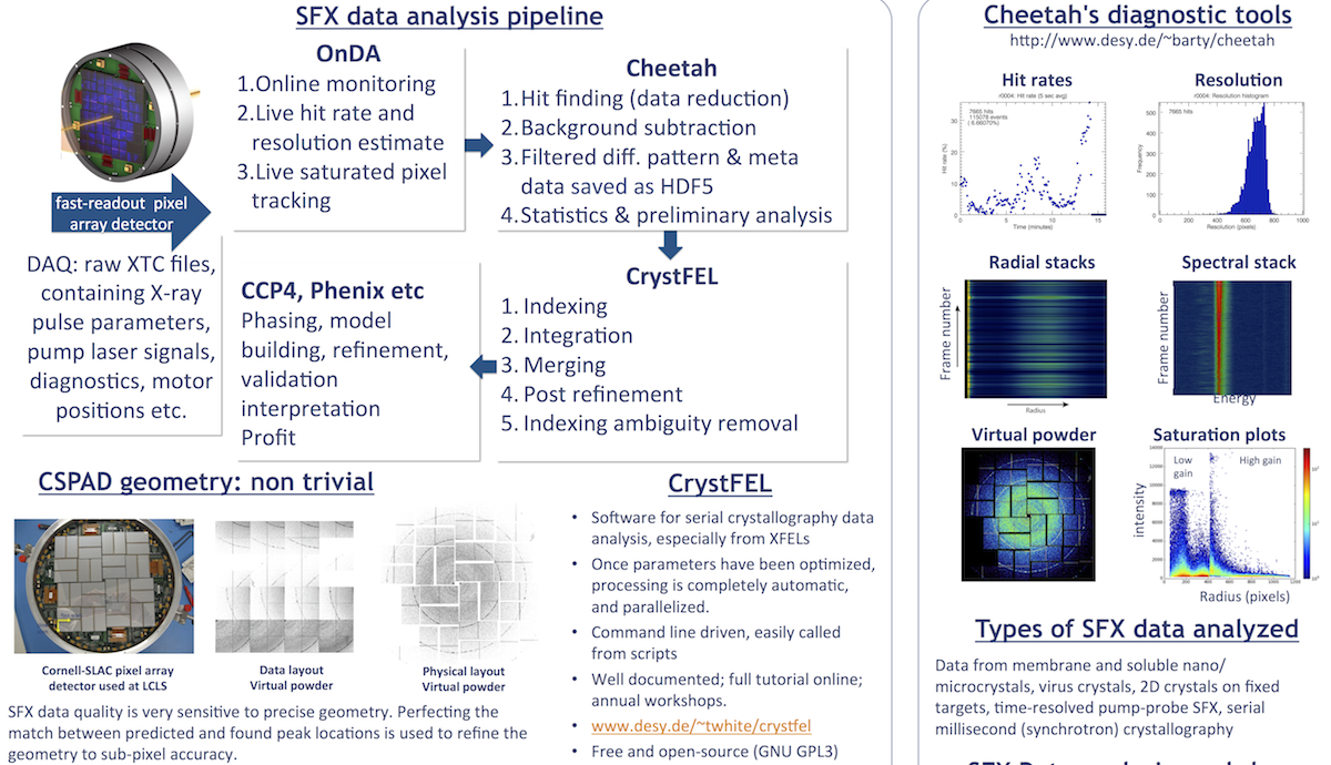
Detectors at CXI
The main detectors used at the Coherent X-ray Imaging (CXI) endstation are Cornell-SLAC pixel array detectors (CSPAD). The "CXI Standard Configuration" in the micron-focus chamber the most common operating mode, which includes 2 full size CSPADs. A CSPAD is also available in the nano-focus chamber, and in the parasitic third chamber (which operates in parallel with the upstream micron-focus chamber).

The CSPAD is an integrating pixel array detector with 1516 x 1516 pixels (110 µm), arranged to cover approximately 18 x18 cm2, with small gaps between panels and a hole in the center for the direct beam. The hole size is variable (from 1.5 - 9.4 mm, but you'd have to refine the geometry if you changed it during an experiment), by moving each quadrant as a solid unit.
The CSPADs offer nearly single photon sensitivity, 103 dynamic range at 8.3 keV with read-out rates matching the top LCLS rate, 120 Hz. (Slower is possible of course).
Two gain setting are available. You can generate a gain mask (a pixel map in HDF5 format) in the Cheetah GUI to choose which regions have low and high gain. Your beamline scientist would have to apply the mask to the CSPAD and you need to allow it some time to equilibrate. This has been used to effectively extend the dynamic range of the CSPAD by working with low gain in the lower resolution regions.
Note that counting detectors such as a Pilatus cannot be used at LCLS; if all photon arrive simultaneously (as they effectively do at LCLS), such a detector will likely count "1".
More information about the CSPAD can be found on the LCLS website.
1. CSPAD Geometry
Since the CSPAD has many individual panels, we must specify how to position each panel in physical space. Notably, there is no particular relationship between real space and the way in which the intensities of pixels are stored on disk. The CrystFEL tutorial (Thomas White, CFEL, DESY) explains:
The arrangement of data in the file is different for a few reasons. Firstly, the exact locations of all the panels might not have been known at the time the data was converted to HDF5 format, and it doesn't make sense to repeat the whole conversion step just to update the estimated position of a panel by a few hundred microns. Secondly, the "raw" data format can match the data output by the DAQ system more closely, making it faster to read out.
...
You need a "CrystFEL detector geometry" file to describe how the raw data format corresponds to the physical locations of the panels.
A common way to specify detector geometry is with CrystFEL ".geom" files, which are explained here. You may also look at the man page of CrystFEL by typing
$ man crystfel_geometry
Since these files are just regular ascii text, you may create your own or edit an existing one by hand, but it is better to use a program to do this as described below.
Unfortunately, Cheetah uses a different geometry format. These are HDF5 files rather than plain text. There are conversion tools for creating a Cheetah HDF5 geometry from a CrystFEL geom file.
Geometry files in various formats are now being shared at LCLS to reduce repetition of work between users. The most recent geometry files can be found here. You should confirm with beamline staff that the one you're about to use corresponds to exactly the same setup, since the configuration may have changed since the last run.
2. Detector name and positions
CxiDsX. If X = number, it is referring to the CSPAD itself; if X is a letter, it is the CSPAD's position.
CxiDs1 is the name of the CSPAD (Cornell SLAC pixel array detector). It can be in the following positions: Talk to your beamline scientist to confirm.
- DSA is the position immediately after the SC01 (aka SC2) chamber for the 100nm focus
- DSB is the position in front of the SC1 chamber
- DSC is the front detector position immediately after the SC1 chamber (1 µm focus)
- DSD is the back detector position (1 µm chamber)
Since run 9 the following configuration is typical
- DS2 in the DSC location
- DS1 in the DSD location
That is, a full CSPAD in both the "front" and "back" locations in the 1 µm chamber. NB. Only one CSPAD fits in the nano-focus chamber at CXI.
More on the CSPAD can be found here.
3. PSANA configuration files
In order to run Cheetah, you will need a proper psana.cfg file. These files are needed by the LCLS-provided libraries that Cheetah must call in order to read XTC data. They are usually located in the .../scratch/<username>/cheetah/process directory by convention. Most importantly, this file specifies which detectors are read into Cheetah. The detector information in particular may need to be changed for different experiment configurations and different instruments. If Cheetah fails to read data, a likely culprit is a line that looks like the following:
You can find details on how to configure this file on the Cheetah website.

4. Optimizing geometry
Detector translation stages do not often move perfectly along the x-ray beam axis. At different detector distances, you will need to correct the detector center. To make these corrections, follow these steps:
1. Run sample with lots of well-separated diffraction spots (such as lysozyme). Best to build up a virtual powder pattern with clear rings, preferably extending to the edge of the detector. Cheetah can produce powder patterns for you automatically; look for files with names like rXXXX-detectorX-classX-sum.h5.
For pixel accuracy, you don't need to index this dataset. You'll just use the rings for now.
2. Open the virtual powder with the CrystFEL hdfsee program with the simple-rings flag; for example:
hdfsee -g geometry.geom -e /data/data --simple-rings=100,140,180,200,300,400,600,800,1000 powderfile.h5
You need to view the power pattern with a geometry file loaded, which means hdfsee must load an unassembled dataset. Check what datasets are available (e.g. /data/data) in your <powder file name>.h5 by running
h5dump -n <powder file name>.h5
3. Enter hdfsee's calibration mode from the toolbar.
Toggle rigid groups with the key "g". If you only need to move the center, press "g" a few times until the whole detector is selected. Use arrow keys to shift the chosen rigid group. Press "s" to save the new geometry file. See the manual pages for hdfsee for more details.
4. Try the new geometry file for indexing, then use CrystFEL's geoptimiser to refine the new geometry to sub-pixel accuracy (depending on the quality, detector coverage and size of the indexed stream).
See the man pages for geoptimiser for more information.
5. Updating Cheetah's geometry file
In your Cheetah ini file, geometry=<filename.h5> points to the pixel map (x, y, z coordinates corresponding to each and every pixel) that map the 64 CSPAD panels into their real-space arrangement. Cheetah needs this file for a number of calculations and for displaying the output in the Cheetah GUI. However, it is best to save CSPAD diffraction data "unassembled" (i.e. without interpolation), so that when you refine the geometry later, you don't have to rerun the hit finding again. Please read about Cheetah's keywords (looked for "assembled") for more details.
To update the geometry pixel map, run make_pixelmap on the CrystFEL geometry file. If make_pixelmap is not in your PATH, download it from CrystFEL's "extra programs" collection.
After your beamtime, please consider (asking your PI to allow) sharing your updated geometry files with the LCLS user community.
References
PREVIOUS: 3. Accessing your data NEXT: 5. Data reduction and hit finding: Cheetah
Back to front page: LCLS serial femtosecond crystallography data analysis instructions


